- 您现在的位置:买卖IC网 > Sheet目录447 > IRFZ24STRRPBF (Vishay Siliconix)MOSFET N-CH 60V 17A D2PAK
�� �
�
�IRFZ24S,� IRFZ24L,� SiHFZ24S,� SiHFZ24S�
�Vishay� Siliconix�
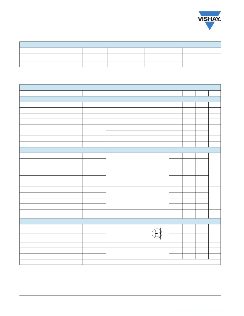
�THERMAL� RESISTANCE� RATINGS�
�PARAMETER�
�Maximum� Junction-to-Ambient�
�(PCB� Mounted,� Steady-State)� a�
�Maximum� Junction-to-Case� (Drain)�
�SYMBOL�
�R� thJA�
�R� thJC�
�TYP.�
�-�
�-�
�MAX.�
�40�
�2.5�
�UNIT�
�°C/W�
�Note�
�a.� When� mounted� on� 1"� square� PCB� (FR-4� or� G-10� material).�
�SPECIFICATIONS� (T� J� =� 25� °C,� unless� otherwise� noted)�
�PARAMETER�
�SYMBOL�
�TEST� CONDITIONS�
�MIN.�
�TYP.�
�MAX.�
�UNIT�
�Static�
�Drain-Source� Breakdown� Voltage�
�V� DS� Temperature� Coefficient�
�Gate-Source� Threshold� Voltage�
�Gate-Source� Leakage�
�Zero� Gate� Voltage� Drain� Current�
�V� DS�
�?� V� DS� /T� J�
�V� GS(th)�
�I� GSS�
�I� DSS�
�V� GS� =� 0,� I� D� =� 250� μA�
�Reference� to� 25� °C,� I� D� =� 1� mA� c�
�V� DS� =� V� GS� ,� I� D� =� 250� μA�
�V� GS� =� ±� 20� V�
�V� DS� =� 60� V,� V� GS� =� 0� V�
�V� DS� =� 48� V,� V� GS� =� 0� V,� T� J� =� 150� °C�
�60�
�-�
�2.0�
�-�
�-�
�-�
�-�
�0.061�
�-�
�-�
�-�
�-�
�-�
�-�
�4.0�
�±� 100�
�25�
�250�
�V�
�V/°C�
�V�
�nA�
�μA�
�Drain-Source� On-State� Resistance�
�R� DS(on)�
�V� GS� =� 10� V�
�I� D� =� 10� A� b�
�-�
�-�
�0.10�
�?�
�Forward� Transconductance�
�g� fs�
�V� DS� =� 25� V,� I� D� =� 10�
�A� d�
�5.5�
�-�
�-�
�S�
�Dynamic�
�Input� Capacitance�
�C� iss�
�V� GS� =� 0� V,�
�-�
�640�
�-�
�Output� Capacitance�
�Reverse� Transfer� Capacitance�
�Total� Gate� Charge�
�C� oss�
�C� rss�
�Q� g�
�V� DS� =� 25� V,�
�f� =� 1.0� MHz,� see� fig.� 5� d�
�-�
�-�
�-�
�360�
�79�
�-�
�-�
�-�
�25�
�pF�
�Gate-Source� Charge�
�Q� gs�
�V� GS� =� 10� V�
�I� D� =� 17� A,� V� DS� =� 48� V,�
�see� fig.� 6� and� 13� b,� c�
�-�
�-�
�5.8�
�nC�
�Gate-Drain� Charge�
�Turn-On� Delay� Time�
�Q� gd�
�t� d(on)�
�-�
�-�
�-�
�13�
�11�
�-�
�Rise� Time�
�Turn-Off� Delay� Time�
�Fall� Time�
�Internal� Source� Inductance�
�t� r�
�t� d(off)�
�t� f�
�L� S�
�V� DD� =� 30� V,� I� D� =� 17� A,�
�R� g� =� 18� ?� ,� R� D� =� 1.7� ?� ,� see� fig.� 10� b,� c�
�Between� lead,� and� center� of� die� contact�
�-�
�-�
�-�
�-�
�58�
�25�
�42�
�7.5�
�-�
�-�
�-�
�-�
�ns�
�nH�
�Drain-Source� Body� Diode� Characteristics�
�Continuous� Source-Drain� Diode� Current�
�Pulsed� Diode� Forward� Current� a�
�I� S�
�I� SM�
�MOSFET� symbol�
�showing� the�
�integral� reverse�
�p� -� n� junction� diode�
�G�
�D�
�S�
�-�
�-�
�-�
�-�
�17�
�68�
�A�
�Body� Diode� Voltage�
�V� SD�
�T� J� =� 25� °C,� I� S� =� 17� A,� V� GS� =� 0�
�V� b�
�-�
�-�
�1.5�
�V�
�Body� Diode� Reverse� Recovery� Time�
�Body� Diode� Reverse� Recovery� Charge�
�t� rr�
�Q� rr�
�T� J� =� 25� °C,� I� F� =� 17� A,� dI/dt� =� 100� A/μs� b,� c�
�-�
�-�
�88�
�290�
�180�
�640�
�ns�
�μC�
�Forward� Turn-On� Time�
�t� on�
�Intrinsic� turn-on� time� is� negligible� (turn-on� is� dominated� by� L� S� and� L� D� )�
�Notes�
�a.� Repetitive� rating;� pulse� width� limited� by� maximum� junction� temperature� (see� fig.� 11).�
�b.� Pulse� width� ?� 300� μs;� duty� cycle� ?� 2� %.�
�c.� Uses� IRFZ24/SiHFZ24� data� and� test� conditions.�
�www.vishay.com�
�2�
�Document� Number:� 90366�
�S11-1063-Rev.� C,� 30-May-11�
�This� document� is� subject� to� change� without� notice.�
�THE� PRODUCTS� DESCRIBED� HEREIN� AND� THIS� DOCUMENT� ARE� SUBJECT� TO� SPECIFIC� DISCLAIMERS,� SET� FORTH� AT� www.vishay.com/doc?91000�
�发布紧急采购,3分钟左右您将得到回复。
相关PDF资料
IRFZ34E
MOSFET N-CH 60V 28A TO-220AB
IRFZ34NL
MOSFET N-CH 55V 29A TO-262
IRFZ34STRLPBF
MOSFET N-CH 60V 30A D2PAK
IRFZ44ESTRL
MOSFET N-CH 60V 48A D2PAK
IRFZ44E
MOSFET N-CH 60V 48A TO-220AB
IRFZ44NSTRR
MOSFET N-CH 55V 49A D2PAK
IRFZ46NSTRL
MOSFET N-CH 55V 53A D2PAK
IRFZ48NL
MOSFET N-CH 55V 64A TO-262
相关代理商/技术参数
IRFZ24V
制造商:IRF 制造商全称:International Rectifier 功能描述:Power MOSFET(Vdss=60V, Rds(on)=60mohm, Id=17A)
IRFZ24VHR
制造商:International Rectifier 功能描述:TRANS MOSFET N-CH 60V 17A 3PIN TO-220AB - Bulk
IRFZ24VL
制造商:未知厂家 制造商全称:未知厂家 功能描述:60V Single N-Channel HEXFET Power MOSFET in a TO-262 package
IRFZ24VLPBF
制造商:IRF 制造商全称:International Rectifier 功能描述:HEXFET Power MOSFET
IRFZ24VPBF
制造商:International Rectifier 功能描述:MOSFET N 60V 17A TO-220 制造商:International Rectifier 功能描述:MOSFET, N, 60V, 17A, TO-220 制造商:International Rectifier 功能描述:MOSFET, N, 60V, 17A, TO-220; Transistor Polarity:N Channel; Continuous Drain Current Id:17A; Drain Source Voltage Vds:60V; On Resistance Rds(on):60mohm; Rds(on) Test Voltage Vgs:10V; Threshold Voltage Vgs Typ:4V; Power Dissipation ;RoHS Compliant: Yes
IRFZ24VS
制造商:未知厂家 制造商全称:未知厂家 功能描述:60V Single N-Channel HEXFET Power MOSFET in a D2-Pak package
IRFZ24VSPBF
制造商:International Rectifier 功能描述:MOSFET N 60V 17A D2-PAK
IRFZ25
制造商:未知厂家 制造商全称:未知厂家 功能描述:TRANSISTOR | MOSFET | N-CHANNEL | 60V V(BR)DSS | 14A I(D) | TO-220AB